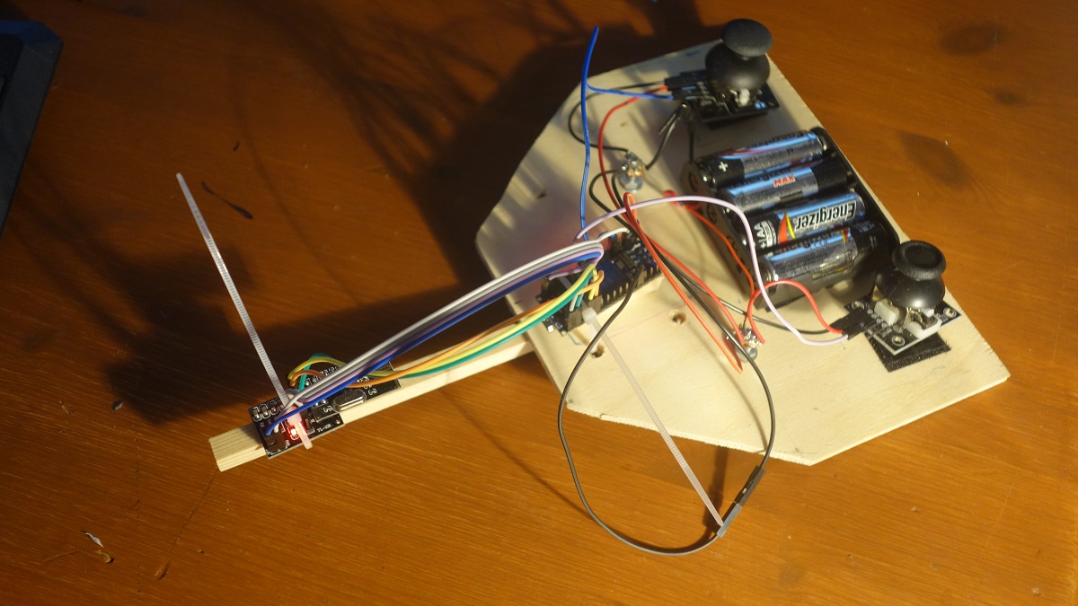
Remote Control Transmitter
The RC system establishes a wireless communication between two Arduino Nano boards using the NRF24 L01 transceiver modules. The modules operate at a frequency of 2.4GHz, which is one of the ISM band which means it is open to use in most of the countries around the World. To achieve a longer range I recommend to use the module nRF24L01+PA+LNA (PA stands for "Power Amplifier" and LNA for "Low-Noise Amplifier") on the transmitter side and the normal nRF24L01 module on the receiver side.
A detailed introduction to the use and programming of the NRF24 Wifi module can be found in my Arduino WIFI tutorial.
Required parts:

1 x Arduino Nano
1 x NRF24L01
2 x Joystick KY-023
1 x battery pack (4 x AA)
Wiring
The NRF24L01 module communicates with the Arduino using SPI protocol. SPI is a synchronous serial communication interface specification used for short-distance communication, primarily in embedded systems. SPI devices communicate in full duplex mode using a master–slave architecture usually with a single master.
The SPI bus specifies the following logic signals:
    SCK : Serial Clock (from master)
    MOSI: Master Out Slave In (data output from master)
    MISO: Master In Slave Out (data output from slave)
    CE  : Chip Enable
    CSN : Chip Select
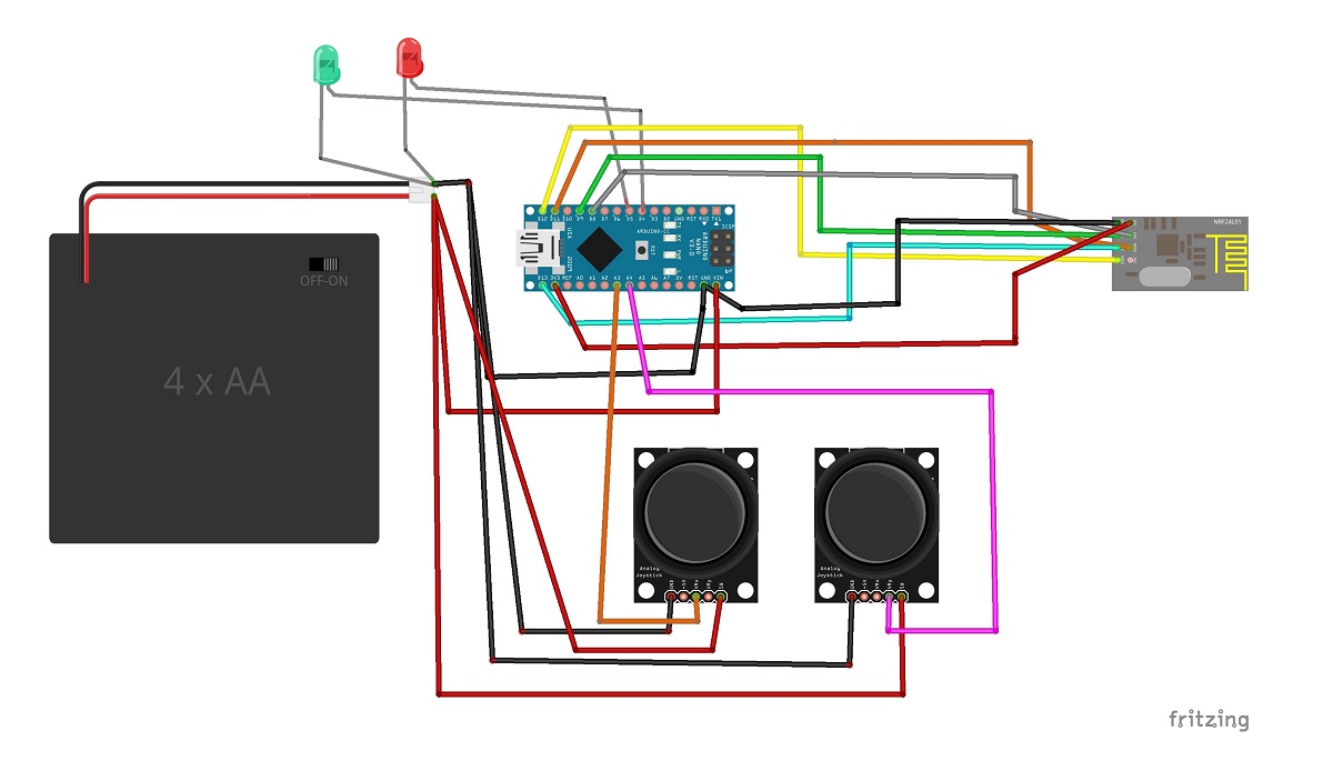
This means for us that the MOSI, MISO, SCK, CE and CSN pins must be connected to their corresponding pins on the microcontroller. Use the same wiring for both sender and receiver.

Pinout
Arduino         Part

VIN             Battery +
GND             Battery -
A3              Joystick 1 VRx
A4              Joystick 2 VRy
D11             NRF24L MOSI
D12             NRF24L MISO
D13             NRF24L SCK
D9              NRF24L CE
D8              NRF24L CSN
+3.3 V          NRF24L VCC
Additionally you have to connect GND of both joysticks with the minus pole of the battery. Also the two minus connections of the LEDs must be connected to the minus pole of the battery (see drawing).
Transmitter Software
/*
* Airboat RC Controller
* Code for transmitter
* (c) Stefan Hager 2023
*/

#include <SPI.h>
#include <nRF24L01.h>
#include <RF24.h>

#define debug 0

// CE is on pin 9
// CSN is on pin 8
RF24 sender(9, 8);

const byte address[7] = "AIRBOAT";

int thrust_raw, rudder_raw;

// the data package which will be used for transmission

struct Data_Struct
{
  int thrust = 0;
  int rudder = 90;
};

Data_Struct data;

void setup()
{
  Serial.begin(9600);
  sender.begin();
  if(sender.isChipConnected())
  {
    Serial.println("Sender starting...");
    sender.setChannel(0x60);
    sender.openWritingPipe(address);
    // important if you power the NRF24 via arduino, higher power levels
    // consume too much power
    sender.setPALevel(0);
    sender.setDataRate(RF24_250KBPS);
    sender.stopListening();
  }
  else
  {
    Serial.println("Error: No responding NRF24 chip found....");
  }
}

void loop()
{
  // read joystick values from A2 = thrust and A3 = rudder

  // thrust_raw and rudder_raw are the value from the analog input
  thrust_raw = analogRead(A3); // will be 0-1023
  rudder_raw = analogRead(A4); // will be 0-1023

  // map thust_raw to vlaues from -255 to 255 (as required for the H-bridge engine controller)
  // -255 ist full thrust reverse, 255 is full thust forward

  data.thrust = map(thrust_raw, 0, 1023, 255, -255);

  // map rudder_raw to vlaues from 0 to 180 (degrees for the rudder servo)

  data.rudder = map(rudder_raw, 0, 1023, 0, 180);

  // transmit values
  sender.write(&data, sizeof(data));
  #ifdef debug
    Serial.print("T: ");
    Serial.print(data.thrust);
    Serial.print(" R:");
    Serial.println(data.rudder);
  #endif
  delay(1000);
}

